Pics of trip to study welding on the Vomit Comet (NO 56k!!)
Posted: 2008-06-14 12:18pm
For the past week I have been in Houston, Texas working on an undergraduate research project for NASA. We are studying how welding in microgravity affects the quality and strength of the resulting weld. I participated as ground crew and did not fly on the aircraft. But that gave me plenty of time to take pictures.
You will also see pictures of the other team from Missouri S&T, known as the Thrusters team. They were planning on studying a new cold-gas thruster using R-134a refrigerant as a propellant. Their ultimate goal is to make a satellite. However, as we will see, they had problems and had to change their experiment in less than 24 hours.
Finally, I have included pictures from various tours of buildings in Houston, some of which require VIP status to get...
Feel free to ask questions.
To download the full images, visit the google picasa web album at http://picasaweb.google.com/3.norton/Mi ... light_2008

This is the Weld Team Experiment. The blue box is the automatic welder. This picture was taken in the new mechanical engineering building on campus in Rolla, MO, before we left.

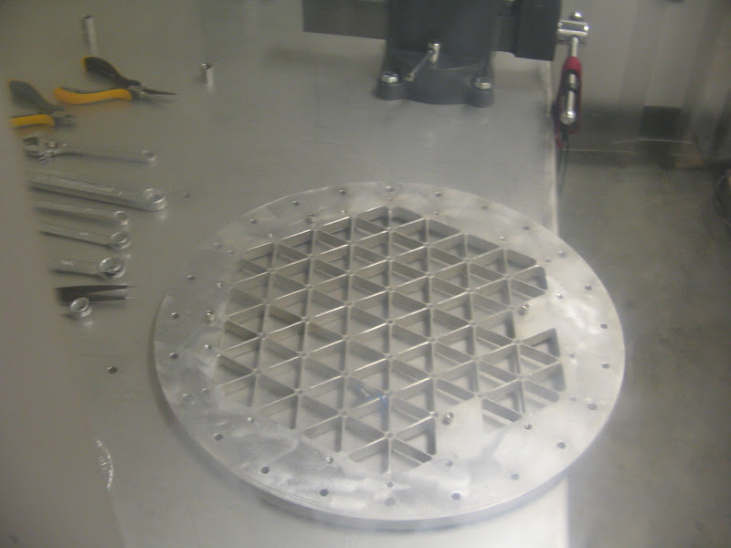
This is the inside of the welding "box" -- All the action takes place in here. The black cylinder is the wire spool, and the weld "gun" is the metal tube that extends below it and appears to touch the metal strips on the bottom. (it doesn't) This is designed to move from right to left along the metal bar, and that entire assembly moves back and forth along the two rods on either side, so the welder can move in two dimensions.
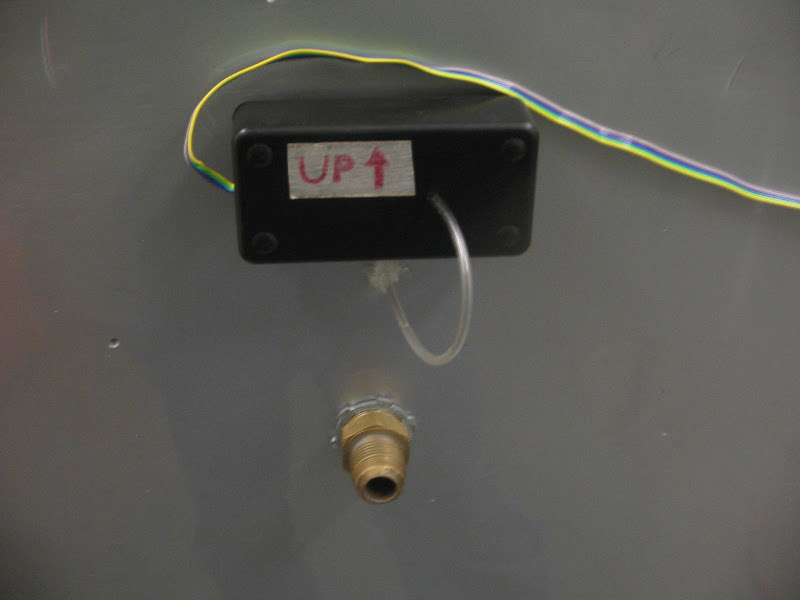
This is a neat little box on the back of the welder compartment. It keeps track of the acceleration being experienced by the welder and the pressure inside the box (that's what the tube is for.) The brass fitting below it is the "outboard vent"-- this is connected to a vent on the outside of the plane, so that smoke and fumes inside the box are pulled out of the plane.

This is a vacuum designed to pull fumes and smoke out of a confined space -- like our welder. We use this in the lab, since the overboard vent is not being used.

This is a basic mock-up of the UMR MR/MRS satellite. The experiment with this pair is that the MR SAT is designed to attempt to fly in formation with the MRS SAT as a target. This was in a different room of the ME building.

This is the fuel tank for the thruster. It stores and heats liquid refrigerant. (The heater is the brown wrap.) The blue ball is a pressure controller.

This is a shot of the thruster assembly of the thruster experiment. The actual thruster part are the two cylinders on the left side that is pointing left. The longer cylinder with the yellow and red wires is the valve that controls the thruster, and the little one is the nozzle. The thruster uses R-134a refrigerant as a propellant. This allows us to store it in the tank in a mostly liquid state (which gives us a much higher density than highly compressed gas and is much safer), and when you heat it, it comes out as a gas (which gives a nice, clean thrust, as opposed to spraying liquid, which comes out of the nozzle in unevenly sized droplets -- not good for precision work.) This was actually taken later, when we were on Ellington Field in Houston.

These are bunny-suits in the small "airlock" section of the small climate-controlled clean room. Photo taken in Rolla, MO.
This was seen inside the clean room, and it appears to be a structural part of the satellite. Photo taken in Rolla, MO

Also inside the clean room was a diagram of how the parts fit in the satellite. Photo taken in Rolla.

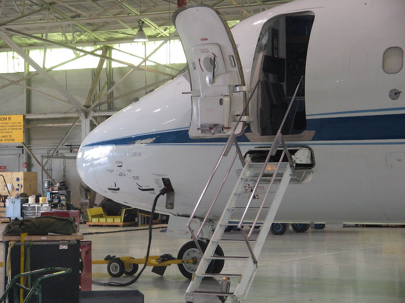
This is the nose of NASA's "Vomit Comet". (They prefer the term "Weightless Wonder" for publicity reasons.) I was unable to move closer to the nose of the aircraft, so this is the best shot I could get.
Another view of the front of the plane, taken a few days later. I hadn't noticed the parabola diagram on the nose before now.

The midsection.

And this is the tail end. Just a side note here, this picture was taken facing north. We were forbidden to take pictures using the east as a back drop, as that was the direction of the military side of the base. We were also advised not to take pictures of aircraft on the ground, as we could inadvertently capture an image of the inner workings of the aircraft (especially the electronics) which is kept secret for security reasons. One of the NASA mentors joked that "If you wander over there to take pictures of an F-16, you will soon be face-to-face with an M-16." I don't think it was entirely a joke.

The aft end of the aircraft. Don't stand here when the engines are on. (stand at least 200 feet back)
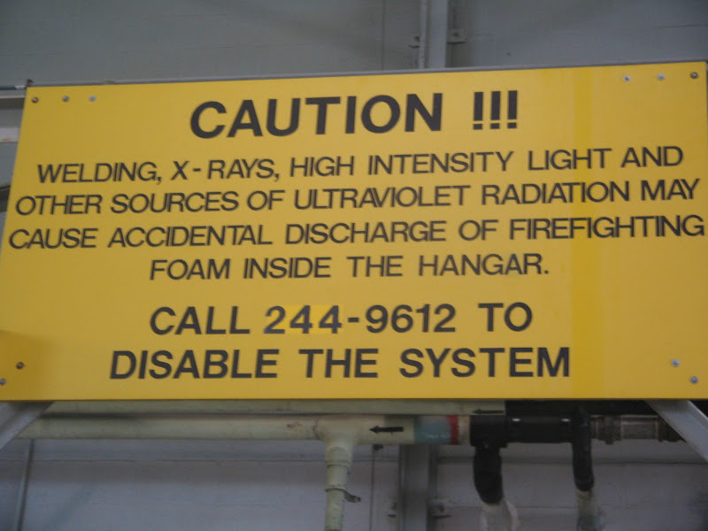
If the sensors in the room detect any sparks or arcing or anything, they will spray the room with 15 feet of water and fire suppressing foam. Thus, we had to work on our welder in a separate room. (YES, air conditioning! -- otherwise you work in the open hanger.)

Sweet! HALON! I feel really safe now!

We added the name of the company who painted our welder for us (for free!), as well our university logo and shamrocks.

And here's the welder, all set up and ready to go in Houston. Well, except for the argon. Sorry for the blurriness. My camera-fu sucks.

This would have been taken to the west. I was going for a shot of the air-traffic control tower. (I guess I got it, too.) I don't know if that handles military and/or civilian traffic.
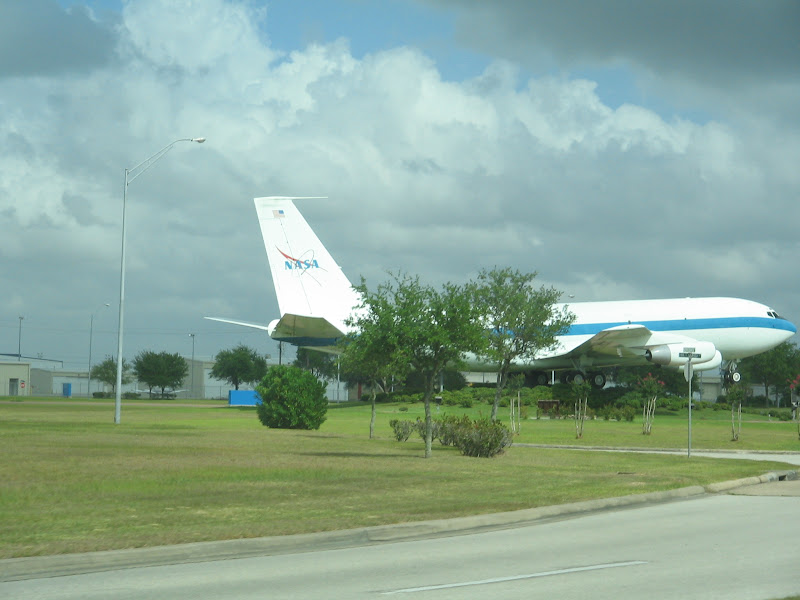
I snapped this on the way out. It's a KC-135 they retired and have set up at the entrance to Ellington Field.

You know that huge swimming pool that astronauts train for spacewalks in? This is it. It used to be open for general tours, but I understand that post-9/11, it requires you to pull a few strings to get into even the tourist section. Fortunately for you, people pulled some strings for me
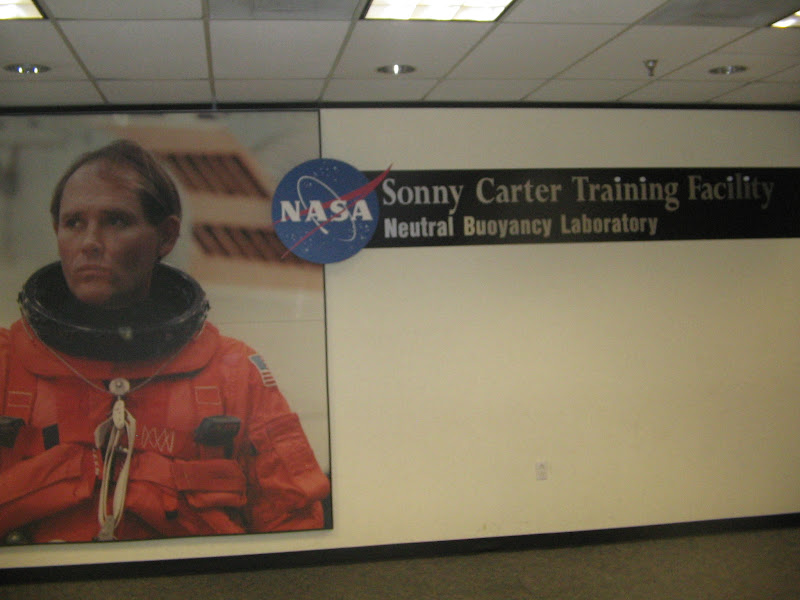
This is the first thing you see as you walk in the door to the NBL.

We got a guided tour. I was pretty busy snapping bad pictures. I got this first.
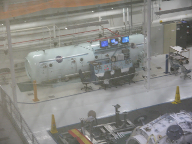
This, I am told, is the hyperbaric chamber. The hypobaric chamber (not pictured) is where those members of the team that are flying went through altitude training. They take you up to 20,000 feet equivalent pressure, and then you take your oxygen mask off and try to do basic arithmetic and memory recall while suffering from hypoxia (lack of oxygen.)

Yes, I was taking a guided tour through the guided tour section, but I was inside the NBL!
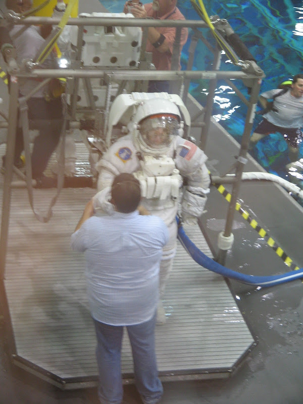
We got really lucky and came when the astronauts were getting out of the pool. They had them stand on a submerged platform attached to a crane, and then they hauled them out of the water. You can't just walk out of the stairs in the pool when you're wearing a 300 lb suit.

And the helmet is off. This is Sandra Magnus, a physics graduate from the University of Missouri-Rolla (my own college) and I got to see her at the Alumni Dinner that night. She shared after dinner about her experiences as an astronaut on STS-112, and how difficult it was to readjust to Earth gravity afterward. She is scheduled for a stay onboard the ISS later this year.

This is the little piece of paper and plastic that lets me do all the cool stuff I do. Usually they check photo ID as well. It was a little hair-raising the first day when I found that my driving permit had expired the week before, but they accepted my university photo ID.

This is outside the Johnson Space Center -- Two T-38 jets usually used for training pilots.
(The Johnson Space Center is a museum/activity center, and the source for some of the upcoming pictures.)

This is the design for the new ship for NASA's new program to reach for the stars, called Project Constellation. Pictured here are the Ares V and I launch vehicles (respectively, in this picture.) These are the rockets that will take us BACK to the moon.

The Faith 7 capsule of the Mercury project, flown by Gordon Cooper.

A Project Gemini EVA.

The practice moon buggy that was used on the Earth. It and it's moon-bound counterpart had a top speed of 10 mph.

Moon rocks. The ruler is for scale, the cube documents the orientation of the rock when it was found on the moon (i.e. the top of the rock on the left, as we see it now, was facing west when it laid on the moon.)

Another moon rock.

A selection of various minerals commonly found on the moon.

If you go to the web album, you can download all ~2 MB of this photo and actually read the entire thing.

Sunday, June 8th, the Thrusters team was working frantically on programing their computer. The valve have two "on" states: startup, which lasts not more than 9 milliseconds, requires 24 volts. Anything longer than that and it will destroy the valve. Normal, sustained operation uses 5 volts. Whatever happened, both valves on the Thruster section blew out. Those puppies cost $1k a piece and it took them 6 months to get them shipped. There was no way they could replace it in one day. You can see a little of the copper wire used for the solenoid sticking out the back of the valve.

This is the second valve, used as a safety. The copper coiling used in the solenoid is quite visible.

The whole group tries to troubleshoot the welder. We had a few problems on Monday with the welder not zeroing itself properly. We tried to modify the zero point electronically and failed, but then found the problem was a bent sensor point. A few seconds bending it back into place with a needle-nose pliers had us in the green again.

The weld compartment is connected to an overboard air vent to evacuate smoke and gases generated during welding. To improve airflow, we drilled an inflow hole and valve. We needed to pull the drilled metal shavings out of a crevice that ran around inside the weld box. (having metal shavings floating around in zero gravity is a bad idea.) The shop vac "wedge" tool didn't have an adapter, so I duct-taped it to the hose. But it was still too wide to fit down in the crevice. We had Subway for lunch earlier that day, and I duct-taped spare straws in parallel into the wedge. It was an ugly duct-taped "stack" on top of the hose, but it worked great, cleaning out the sides of the weld compartment with minimal fuss.

And we're loading the welder. But wait! Where's the welder?

As they were loading the welder, they pulled on the legs to move it into place, and one of the welds failed. From across the flight deck, the Operations Manager for the Reduced Gravity Office said in an ice cold voice, "What was that?" His name is Dom (short for Dominic), but in this context his name is GOD. We offloaded the welder and he told us that given that one of our "certified" welds had failed in one gravity, he couldn't trust any our welds, on either of our projects, at accelerations up to the theoretical maximum of 9 Gs. So we had to find another way mount our welder. Do you know that it would take 16 half-inch bolts made of grade 8 steel to re-secure the legs of a 300 pound welder against an acceleration 9 gravities using a safety factor of four? We ended up ditching the entire problematic lower half of the structure, and just bolted the welder (which would have sat on the lower tray) directly to the floor of the aircraft.

Duct tape -- Government style. Drab olive grey, twice as wide as a regular roll of duct tape, and about the diameter of a basketball. Everything's bigger in Texas.

THAT'S OUR WELDER BEING LOADED ONTO THE PLANE! We got the welds that didn't fail X-rayed, and they were good. Both teams were cleared to fly, with some structural modifications.

GREEN LIGHT for both Missouri teams!

Moving the welder from the forklift to the plane.
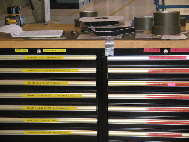
The official tool set. These are inventoried at the end of every shift, to prevent them from being lost. In the aircraft industry, it is very important to keep track of all items, as loose or lost items could be sucked into a plane engine and cost millions of dollars in damage and potential injury or loss of life. This is called FOD, or Foreign Object Damage. If any one of these tools is missing before the flight, the plane doesn't fly.

I was surprised to see this on the sign for the plaza next to my hotel. My mother is part Czech, and she sometimes makes Kolache. Kolache is plural for "cake" in Czech. In America it refers to a special form of pastry which can have a variety of fillings.

Getting ready in the parking lot the day of the flight.

The flyers spent a lot of time in this room the day of the flight.

A couple of the flyers in front of the plane.

Government work is all the same: hurry up and wait. Here we're just chatting before briefings start.

A T-38 training jet taxiing back home.

The WB-57F, used for high altitude research. The wings are huge.

Another shot of the WB-57F. The nose can house up to 500 lbs of instruments. Sorry it's a little grainy, I had to use digital zoom to get this.

Dead on shot of the WB-57F, taxiing in. Again, I used the digital zoom.

I helped change the plates between flights. I forgot to photograph them right when we opened the box (not that we needed to, but if I was going to photograph them, then would have been optimal). The first two were done in one gravity. (the first one didn't have argon shielding gas on it, so it's shot.) The rest were done in zero-g. They look terrible.

Here's a shot on board the aircraft while we were switching plates, looking forward.

A shot towards the aft of the plane. Passengers enter and exit through this hatchway.

The Thrusters team abandoned most of their experiment when the expensive solenoid valves failed, and they planned out a method to test the airtrack they were going to run their experiment on in about an hour. It took them 20 minutes to execute it. This elbow joint acts as a nozzle that will expel nitrogen gas that will push against the spring attached with the red zip tie. Theoretically.

This is a crude ruler drawn by the airtrack to allow the experimenters to see if the movable tray moves at all. If I understand correctly, the nozzle failed to move the movable tray, and they think that indicates that the airtrack failed.

The control mechanisms were very simple: two control valves and a gauge. One valve controls the flow of nitrogen to the airtrack, and one controls the nozzle. The gauge measures the pressure in the line.

After the leg broke, we removed the welder on top and looked at the lower compartments. The welder did a really shoddy job of it, tack welding the whole thing together with little penetration of the weld. And he left the spacer in! (bottom left of center plate) That's supposed to be temporary!

First shot of the second set of welds, after we opened the box. Notice all the dust and powder in the compartment, that was sucked out of the fire extinguisher by the pressure difference between the fire extinguisher and the pressure at 20,000 feet outside the plane. Maybe that's why we got horrible welds.

This was the first tray on the second flight. The number of G's experienced during the weld is marked to the left.

This is the second tray from the second flight. 7 Zero G welds, one Lunar gravity weld, and one Martian gravity weld.

We purchased a banner to hang in the shop we worked in, like many other teams did.

It's a nice view from the loading bay of the aircraft. The man in blue is Doug Goforth, the program facilitator

Looking down into the hanger bay while offloading.

Entering LBJ Space Center...
Third stage and up of Apollo on the left, Mercury on the right, the F1 main engine for the Saturn V between the two, and the white on is the J-2, used on the second Saturn V stage

They keep a Saturn V disassembled by stages in this building.

Yeah, it's big.

The service module and up.

The third stage engine

That's an F-1 standing up. And yes, that's me leaning against it.

That's a friend of mine next to a J-2 engine, used on the second stage.

This is the third stage of the Saturn V.

NASA had BIG vacuum chambers built in the 1960s. It's so big, they build the chamber first and then the rest of the building around it. The door alone weighs 40 tons, but is well balanced enough for two people to move it. The chamber goes down to half a torr in about 12 hours. I forgot how big it was though. They did fit the entire command and service module in there for testing.

Another picture of the door and chamber extending above it.

Material Safety Data Sheets (MSDS): each sheet is 7 - 10 pages long and contains information about one chemical and its hazards (flammability, toxicity to humans and other hazards.) The podium on the left is compounds 'A' thru 'C

This is the mission control for the Shuttle. They were on mission with STS-124 at the time. No flash photography!

Another blurry shot of mission control, before some idiot used their flash and we had to put the cameras away. That would be why I don't have pics of ISS control.

This is the historic mission control room for Apollo. Most tourists only got to see this from the viewing room behind it, but our researcher VIP status allowed us into the actual control room, sit down, and poke around.

A closer look at one of the consoles. There was a lot of historic memorabilia in the room that I was unable to find time to photgraph. On the left side of the room was a small mirror presented on a plaque to the mission controllers, which, I am told, Jim Lowell was looking through when he saw that the service module was leaking. On the right was a flag carried to the moon by Apollo 17.

A rotary phone built into the console. Our tour guides complained that some of the tourists they've had didn't didn't know what a rotary phone was. I myself have only limited experience with them, but at least I know what it is and how to work it.

The consoles were also hooked into a pneumatic cylinder delivery system, which allowed paper hardcopies to be transfered easily between rooms in the building.

Who do astronauts call when they have a problem? Houston. Who does Houston call when they have a problem? The Department of Defense, I believe. (The presidential hotline, I am told, was nondescript.)

There's a lot of floorspace devoted to simulating work inside the ISS and the space shuttle


Full shuttle in front, shuttle nose only behind. The smaller model can be rotated 90 degrees into launch configuration.
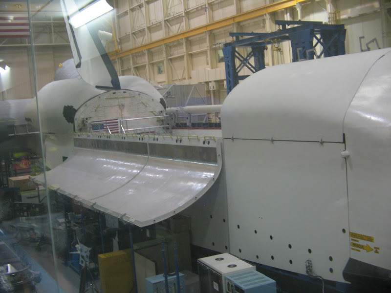
Notice it has no wings, since they are not used in simulations.

Manipulator Arm studies. That's all I have! The end.
You will also see pictures of the other team from Missouri S&T, known as the Thrusters team. They were planning on studying a new cold-gas thruster using R-134a refrigerant as a propellant. Their ultimate goal is to make a satellite. However, as we will see, they had problems and had to change their experiment in less than 24 hours.
Finally, I have included pictures from various tours of buildings in Houston, some of which require VIP status to get...
Feel free to ask questions.
To download the full images, visit the google picasa web album at http://picasaweb.google.com/3.norton/Mi ... light_2008
This is the Weld Team Experiment. The blue box is the automatic welder. This picture was taken in the new mechanical engineering building on campus in Rolla, MO, before we left.
This is the inside of the welding "box" -- All the action takes place in here. The black cylinder is the wire spool, and the weld "gun" is the metal tube that extends below it and appears to touch the metal strips on the bottom. (it doesn't) This is designed to move from right to left along the metal bar, and that entire assembly moves back and forth along the two rods on either side, so the welder can move in two dimensions.
This is a neat little box on the back of the welder compartment. It keeps track of the acceleration being experienced by the welder and the pressure inside the box (that's what the tube is for.) The brass fitting below it is the "outboard vent"-- this is connected to a vent on the outside of the plane, so that smoke and fumes inside the box are pulled out of the plane.
This is a vacuum designed to pull fumes and smoke out of a confined space -- like our welder. We use this in the lab, since the overboard vent is not being used.
This is a basic mock-up of the UMR MR/MRS satellite. The experiment with this pair is that the MR SAT is designed to attempt to fly in formation with the MRS SAT as a target. This was in a different room of the ME building.
This is the fuel tank for the thruster. It stores and heats liquid refrigerant. (The heater is the brown wrap.) The blue ball is a pressure controller.
This is a shot of the thruster assembly of the thruster experiment. The actual thruster part are the two cylinders on the left side that is pointing left. The longer cylinder with the yellow and red wires is the valve that controls the thruster, and the little one is the nozzle. The thruster uses R-134a refrigerant as a propellant. This allows us to store it in the tank in a mostly liquid state (which gives us a much higher density than highly compressed gas and is much safer), and when you heat it, it comes out as a gas (which gives a nice, clean thrust, as opposed to spraying liquid, which comes out of the nozzle in unevenly sized droplets -- not good for precision work.) This was actually taken later, when we were on Ellington Field in Houston.
These are bunny-suits in the small "airlock" section of the small climate-controlled clean room. Photo taken in Rolla, MO.
This was seen inside the clean room, and it appears to be a structural part of the satellite. Photo taken in Rolla, MO
Also inside the clean room was a diagram of how the parts fit in the satellite. Photo taken in Rolla.
This is the nose of NASA's "Vomit Comet". (They prefer the term "Weightless Wonder" for publicity reasons.) I was unable to move closer to the nose of the aircraft, so this is the best shot I could get.
Another view of the front of the plane, taken a few days later. I hadn't noticed the parabola diagram on the nose before now.
The midsection.
And this is the tail end. Just a side note here, this picture was taken facing north. We were forbidden to take pictures using the east as a back drop, as that was the direction of the military side of the base. We were also advised not to take pictures of aircraft on the ground, as we could inadvertently capture an image of the inner workings of the aircraft (especially the electronics) which is kept secret for security reasons. One of the NASA mentors joked that "If you wander over there to take pictures of an F-16, you will soon be face-to-face with an M-16." I don't think it was entirely a joke.
The aft end of the aircraft. Don't stand here when the engines are on. (stand at least 200 feet back)
If the sensors in the room detect any sparks or arcing or anything, they will spray the room with 15 feet of water and fire suppressing foam. Thus, we had to work on our welder in a separate room. (YES, air conditioning! -- otherwise you work in the open hanger.)
Sweet! HALON! I feel really safe now!
We added the name of the company who painted our welder for us (for free!), as well our university logo and shamrocks.
And here's the welder, all set up and ready to go in Houston. Well, except for the argon. Sorry for the blurriness. My camera-fu sucks.
This would have been taken to the west. I was going for a shot of the air-traffic control tower. (I guess I got it, too.) I don't know if that handles military and/or civilian traffic.
I snapped this on the way out. It's a KC-135 they retired and have set up at the entrance to Ellington Field.
You know that huge swimming pool that astronauts train for spacewalks in? This is it. It used to be open for general tours, but I understand that post-9/11, it requires you to pull a few strings to get into even the tourist section. Fortunately for you, people pulled some strings for me
This is the first thing you see as you walk in the door to the NBL.
We got a guided tour. I was pretty busy snapping bad pictures. I got this first.
This, I am told, is the hyperbaric chamber. The hypobaric chamber (not pictured) is where those members of the team that are flying went through altitude training. They take you up to 20,000 feet equivalent pressure, and then you take your oxygen mask off and try to do basic arithmetic and memory recall while suffering from hypoxia (lack of oxygen.)
Yes, I was taking a guided tour through the guided tour section, but I was inside the NBL!
We got really lucky and came when the astronauts were getting out of the pool. They had them stand on a submerged platform attached to a crane, and then they hauled them out of the water. You can't just walk out of the stairs in the pool when you're wearing a 300 lb suit.
And the helmet is off. This is Sandra Magnus, a physics graduate from the University of Missouri-Rolla (my own college) and I got to see her at the Alumni Dinner that night. She shared after dinner about her experiences as an astronaut on STS-112, and how difficult it was to readjust to Earth gravity afterward. She is scheduled for a stay onboard the ISS later this year.
This is the little piece of paper and plastic that lets me do all the cool stuff I do. Usually they check photo ID as well. It was a little hair-raising the first day when I found that my driving permit had expired the week before, but they accepted my university photo ID.
This is outside the Johnson Space Center -- Two T-38 jets usually used for training pilots.
(The Johnson Space Center is a museum/activity center, and the source for some of the upcoming pictures.)
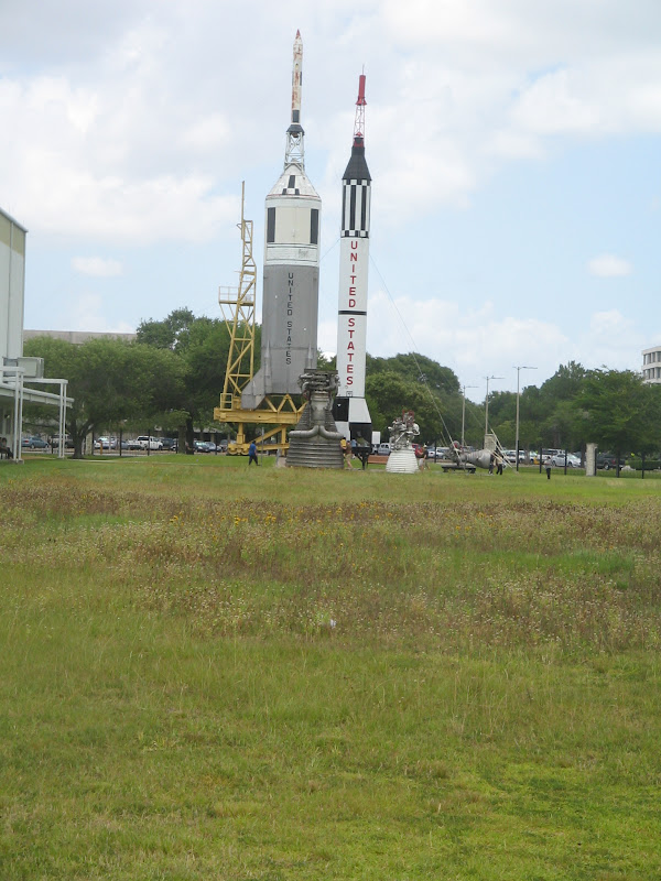
This is the design for the new ship for NASA's new program to reach for the stars, called Project Constellation. Pictured here are the Ares V and I launch vehicles (respectively, in this picture.) These are the rockets that will take us BACK to the moon.
The Faith 7 capsule of the Mercury project, flown by Gordon Cooper.
A Project Gemini EVA.
The practice moon buggy that was used on the Earth. It and it's moon-bound counterpart had a top speed of 10 mph.
Moon rocks. The ruler is for scale, the cube documents the orientation of the rock when it was found on the moon (i.e. the top of the rock on the left, as we see it now, was facing west when it laid on the moon.)
Another moon rock.
A selection of various minerals commonly found on the moon.
If you go to the web album, you can download all ~2 MB of this photo and actually read the entire thing.
Sunday, June 8th, the Thrusters team was working frantically on programing their computer. The valve have two "on" states: startup, which lasts not more than 9 milliseconds, requires 24 volts. Anything longer than that and it will destroy the valve. Normal, sustained operation uses 5 volts. Whatever happened, both valves on the Thruster section blew out. Those puppies cost $1k a piece and it took them 6 months to get them shipped. There was no way they could replace it in one day. You can see a little of the copper wire used for the solenoid sticking out the back of the valve.
This is the second valve, used as a safety. The copper coiling used in the solenoid is quite visible.
The whole group tries to troubleshoot the welder. We had a few problems on Monday with the welder not zeroing itself properly. We tried to modify the zero point electronically and failed, but then found the problem was a bent sensor point. A few seconds bending it back into place with a needle-nose pliers had us in the green again.
The weld compartment is connected to an overboard air vent to evacuate smoke and gases generated during welding. To improve airflow, we drilled an inflow hole and valve. We needed to pull the drilled metal shavings out of a crevice that ran around inside the weld box. (having metal shavings floating around in zero gravity is a bad idea.) The shop vac "wedge" tool didn't have an adapter, so I duct-taped it to the hose. But it was still too wide to fit down in the crevice. We had Subway for lunch earlier that day, and I duct-taped spare straws in parallel into the wedge. It was an ugly duct-taped "stack" on top of the hose, but it worked great, cleaning out the sides of the weld compartment with minimal fuss.
And we're loading the welder. But wait! Where's the welder?
As they were loading the welder, they pulled on the legs to move it into place, and one of the welds failed. From across the flight deck, the Operations Manager for the Reduced Gravity Office said in an ice cold voice, "What was that?" His name is Dom (short for Dominic), but in this context his name is GOD. We offloaded the welder and he told us that given that one of our "certified" welds had failed in one gravity, he couldn't trust any our welds, on either of our projects, at accelerations up to the theoretical maximum of 9 Gs. So we had to find another way mount our welder. Do you know that it would take 16 half-inch bolts made of grade 8 steel to re-secure the legs of a 300 pound welder against an acceleration 9 gravities using a safety factor of four? We ended up ditching the entire problematic lower half of the structure, and just bolted the welder (which would have sat on the lower tray) directly to the floor of the aircraft.
Duct tape -- Government style. Drab olive grey, twice as wide as a regular roll of duct tape, and about the diameter of a basketball. Everything's bigger in Texas.
THAT'S OUR WELDER BEING LOADED ONTO THE PLANE! We got the welds that didn't fail X-rayed, and they were good. Both teams were cleared to fly, with some structural modifications.
GREEN LIGHT for both Missouri teams!
Moving the welder from the forklift to the plane.
The official tool set. These are inventoried at the end of every shift, to prevent them from being lost. In the aircraft industry, it is very important to keep track of all items, as loose or lost items could be sucked into a plane engine and cost millions of dollars in damage and potential injury or loss of life. This is called FOD, or Foreign Object Damage. If any one of these tools is missing before the flight, the plane doesn't fly.
I was surprised to see this on the sign for the plaza next to my hotel. My mother is part Czech, and she sometimes makes Kolache. Kolache is plural for "cake" in Czech. In America it refers to a special form of pastry which can have a variety of fillings.
Getting ready in the parking lot the day of the flight.
The flyers spent a lot of time in this room the day of the flight.
A couple of the flyers in front of the plane.
Government work is all the same: hurry up and wait. Here we're just chatting before briefings start.
A T-38 training jet taxiing back home.
The WB-57F, used for high altitude research. The wings are huge.
Another shot of the WB-57F. The nose can house up to 500 lbs of instruments. Sorry it's a little grainy, I had to use digital zoom to get this.
Dead on shot of the WB-57F, taxiing in. Again, I used the digital zoom.
I helped change the plates between flights. I forgot to photograph them right when we opened the box (not that we needed to, but if I was going to photograph them, then would have been optimal). The first two were done in one gravity. (the first one didn't have argon shielding gas on it, so it's shot.) The rest were done in zero-g. They look terrible.
Here's a shot on board the aircraft while we were switching plates, looking forward.
A shot towards the aft of the plane. Passengers enter and exit through this hatchway.
The Thrusters team abandoned most of their experiment when the expensive solenoid valves failed, and they planned out a method to test the airtrack they were going to run their experiment on in about an hour. It took them 20 minutes to execute it. This elbow joint acts as a nozzle that will expel nitrogen gas that will push against the spring attached with the red zip tie. Theoretically.
This is a crude ruler drawn by the airtrack to allow the experimenters to see if the movable tray moves at all. If I understand correctly, the nozzle failed to move the movable tray, and they think that indicates that the airtrack failed.
The control mechanisms were very simple: two control valves and a gauge. One valve controls the flow of nitrogen to the airtrack, and one controls the nozzle. The gauge measures the pressure in the line.
After the leg broke, we removed the welder on top and looked at the lower compartments. The welder did a really shoddy job of it, tack welding the whole thing together with little penetration of the weld. And he left the spacer in! (bottom left of center plate) That's supposed to be temporary!
First shot of the second set of welds, after we opened the box. Notice all the dust and powder in the compartment, that was sucked out of the fire extinguisher by the pressure difference between the fire extinguisher and the pressure at 20,000 feet outside the plane. Maybe that's why we got horrible welds.
This was the first tray on the second flight. The number of G's experienced during the weld is marked to the left.
This is the second tray from the second flight. 7 Zero G welds, one Lunar gravity weld, and one Martian gravity weld.
We purchased a banner to hang in the shop we worked in, like many other teams did.
It's a nice view from the loading bay of the aircraft. The man in blue is Doug Goforth, the program facilitator
Looking down into the hanger bay while offloading.
Entering LBJ Space Center...
Third stage and up of Apollo on the left, Mercury on the right, the F1 main engine for the Saturn V between the two, and the white on is the J-2, used on the second Saturn V stage
They keep a Saturn V disassembled by stages in this building.
Yeah, it's big.
The service module and up.
The third stage engine
That's an F-1 standing up. And yes, that's me leaning against it.
That's a friend of mine next to a J-2 engine, used on the second stage.
This is the third stage of the Saturn V.
NASA had BIG vacuum chambers built in the 1960s. It's so big, they build the chamber first and then the rest of the building around it. The door alone weighs 40 tons, but is well balanced enough for two people to move it. The chamber goes down to half a torr in about 12 hours. I forgot how big it was though. They did fit the entire command and service module in there for testing.
Another picture of the door and chamber extending above it.
Material Safety Data Sheets (MSDS): each sheet is 7 - 10 pages long and contains information about one chemical and its hazards (flammability, toxicity to humans and other hazards.) The podium on the left is compounds 'A' thru 'C
This is the mission control for the Shuttle. They were on mission with STS-124 at the time. No flash photography!
Another blurry shot of mission control, before some idiot used their flash and we had to put the cameras away. That would be why I don't have pics of ISS control.
This is the historic mission control room for Apollo. Most tourists only got to see this from the viewing room behind it, but our researcher VIP status allowed us into the actual control room, sit down, and poke around.
A closer look at one of the consoles. There was a lot of historic memorabilia in the room that I was unable to find time to photgraph. On the left side of the room was a small mirror presented on a plaque to the mission controllers, which, I am told, Jim Lowell was looking through when he saw that the service module was leaking. On the right was a flag carried to the moon by Apollo 17.
A rotary phone built into the console. Our tour guides complained that some of the tourists they've had didn't didn't know what a rotary phone was. I myself have only limited experience with them, but at least I know what it is and how to work it.
The consoles were also hooked into a pneumatic cylinder delivery system, which allowed paper hardcopies to be transfered easily between rooms in the building.
Who do astronauts call when they have a problem? Houston. Who does Houston call when they have a problem? The Department of Defense, I believe. (The presidential hotline, I am told, was nondescript.)
There's a lot of floorspace devoted to simulating work inside the ISS and the space shuttle
Full shuttle in front, shuttle nose only behind. The smaller model can be rotated 90 degrees into launch configuration.
Notice it has no wings, since they are not used in simulations.
Manipulator Arm studies. That's all I have! The end.
